More patients have been filed by Nintendo and are now public for all to view. We have everything you need to know down below, but if you feel like reading the actual patient application you can do so here.
ABSTRACT: An example accessory can be attached to an information processing device. The accessory includes a housing, a movable operation section, and a movable portion. An inside of the housing is visible from an outside thereof through at least a portion thereof. At least a portion of the operation section is exposed on the outside of the housing. The movable portion is placed at a position inside the housing that is visible from the outside of the housing through the portion of the housing. A position and/or an attitude of the movable portion changes in response to the operation section being operated.
BACKGROUND AND SUMMARY There are conventional accessories which, when connected to a portable device, add functions to the portable device. For example, there are techniques where an external controller as an accessory is connected to a connector provided on a controller of a game device. This enables a wider variety of game operations using two controllers.
Conventional accessories have a circuit configuration for communicating with a portable device or a circuit configuration for performing an information process for generating information to be transmitted to a portable device, and there has been room for improvement in simplifying the configuration of the accessories.
Thus, the present specification discloses an accessory, an information processing device, an information processing system, a storage medium storing an information processing program, an operation determination method and a process performing method, with which it is possible to simplify the configuration of the accessory.
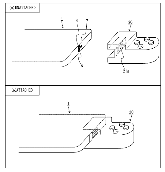
FIG. 8 shows an example operation device before and after it is attached to a portable device;
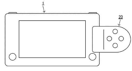
FIG. 9 shows an example configuration where an operation device is attached to a portable device;
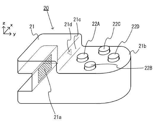
FIG. 6 shows the external appearance of a non-limiting example operation device;
As shown in FIG. 6, a hole (opening portion) 21a is formed in the housing 21. Thus, the operation device 20 is configured so that the inside (the inner side) of the housing 21 can be seen through the hole 21a. Note that the housing 21 may have any configuration such that the inside of the housing 21 is visible from the outside through a predetermined portion of the housing 21. For example, in other embodiments, the predetermined portion may be formed by a transparent member instead of the provision of the hole 21a in the predetermined portion.
Here, in the present embodiment, a reference marker 21d is provided on a wall surface on the inside of the housing 21 (the inner wall surface of a surface 21c in FIG. 6). Movable portions 23A to 23D to be described later are provided on the inside of the housing 21 (see FIG. 7). The hole 21a is formed at such a position that the movable portions 23A to 23D and the reference marker 21d are visible when one sees the inside of the housing 21 from the outside of the housing 21 through the hole 21a.
Advertisement. Scroll to continue reading.
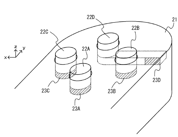
FIG. 7 shows an example internal configuration of the operation device shown in FIG. 6;
FIG. 7 shows an example internal configuration of the operation device shown in FIG. 6. Note that FIG. 7 shows only a part of the configuration inside the housing 21. As shown in FIG. 7, the operation device 20 includes the movable portions 23A to 23D provided inside the housing 21. Note that where the movable portions 23A to 23D are not distinguished from each other, the designation “movable portion 23” may be used to refer to any of the movable portions 23A to 23D.
As shown in FIG. 7, the movable portions 23A to 23D are connected to the operation buttons 22A to 22D, respectively. That is, the movable portion 23A is connected to the operation button 22A, the movable portion 23B to the operation button 22B, the movable portion 23C to the operation button 22C, and the movable portion 23D to the operation button 22D. The movable portion 23 moves (downward in the present embodiment) in response to an operation on the operation button 22 connected thereto. In the present embodiment, each operation button and a movable portion connected thereto are configured as an integral part. Note however that the movable portion may be configured so as to be moved in accordance with the movement of the operation button, and an operation button and a movable portion connected thereto may be separate parts in other embodiments.
In the present embodiment, at least a portion of the movable portion 23 (the hatched area shown in FIG. 7: hereinafter referred to as a “recognition portion”) is of a material (color) such that the infrared camera 4 can distinguish this portion from other portions (other than the portion of the reference marker 21d) of the wall surface on the inside of the housing 21. The recognition portion may be of a retroreflective material, for example. Then, the infrared light from the illuminating section 7 is reflected more toward the infrared camera 4, making it easier for the infrared camera 4 to recognize the recognition portion. This also makes it easier for the infrared camera 4 to recognize a recognition portion that is located away from the infrared camera 4. The movable portion 23 is connected to the lower portion of the operation button 22. Here, for each of the movable portions 23A to 23C, the recognition portion is placed under (directly below) the corresponding operation button 22. For the movable portion 23D, on the other hand, the recognition portion is displaced from a position that is directly below the corresponding operation button 22D (see FIG. 7). That is, the recognition portions of the movable portions 23A to 23D are arranged so that the recognition portions are visible through the hole 21a.
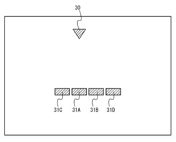
FIG. 11 shows an example captured image obtained by an infrared camera;
FIG. 11 shows an example captured image obtained by the infrared camera 4. The captured image shown in FIG. 11 is an image to be obtained when the operation buttons 22A to 22D are not operated (in the unoperated state). As shown in FIG. 11, the captured image includes an image (reference marker image) 30 of the reference marker 21d and images (movable portion images) 31A to 31D of movable portions 23A to 23D. Thus, the reference marker 21d and the movable portions 23A to 23D are placed at such positions as to be included in the image-capturing range of the infrared camera 4, with the operation device 20 attached to the portable device 1. Thus, with the operation device 20 connected to the portable device 1, the infrared camera 4 can capture an image of the reference marker 21d and the movable portions 23A to 23D inside the housing 21 through the hole 21a of the housing 21. That is, the following members (a) to (d) are placed at such positions that the infrared camera 4 can capture an image of the reference marker 21d and the movable portions 23A to 23D in such a state as described above:
(a) infrared camera 4 of portable device 1;
(b) hole 21a of housing 21 of controller device 20;
(c) reference marker 21d of controller device 20; and
(d) movable portions 23A to 23D of controller device 20.
Advertisement. Scroll to continue reading.
| Original content here is published under these license terms: | X | |
| License Type: | Read Only | |
| License Abstract: | You may read the original content in the context in which it is published (at this web address). No other copying or use is permitted without written agreement from the author. | |

